Bend Sheet Metal Creo

Sheet Metal Design Intent Objects For Sheetmetal Design Ptc Learning Connector

Twist Command Sheet Metal Creo 2 0 Youtube

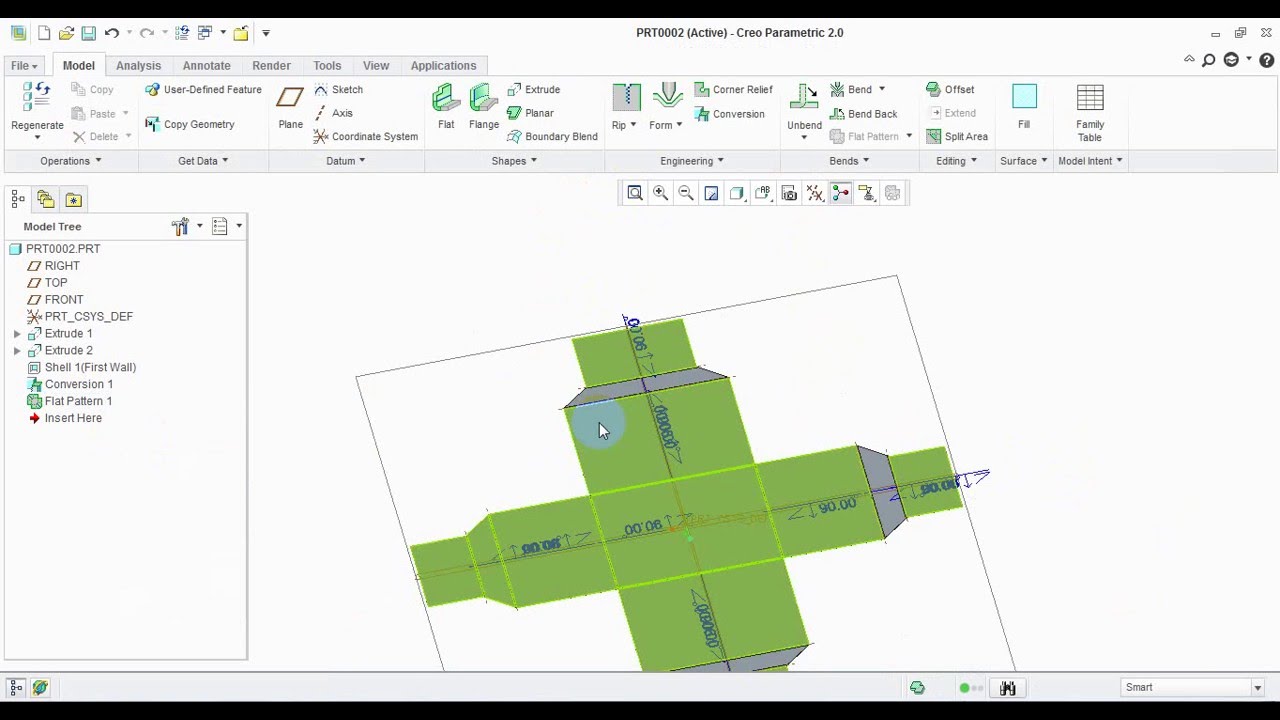
Creo Parametric Sheetmetal Planar Bends Youtube
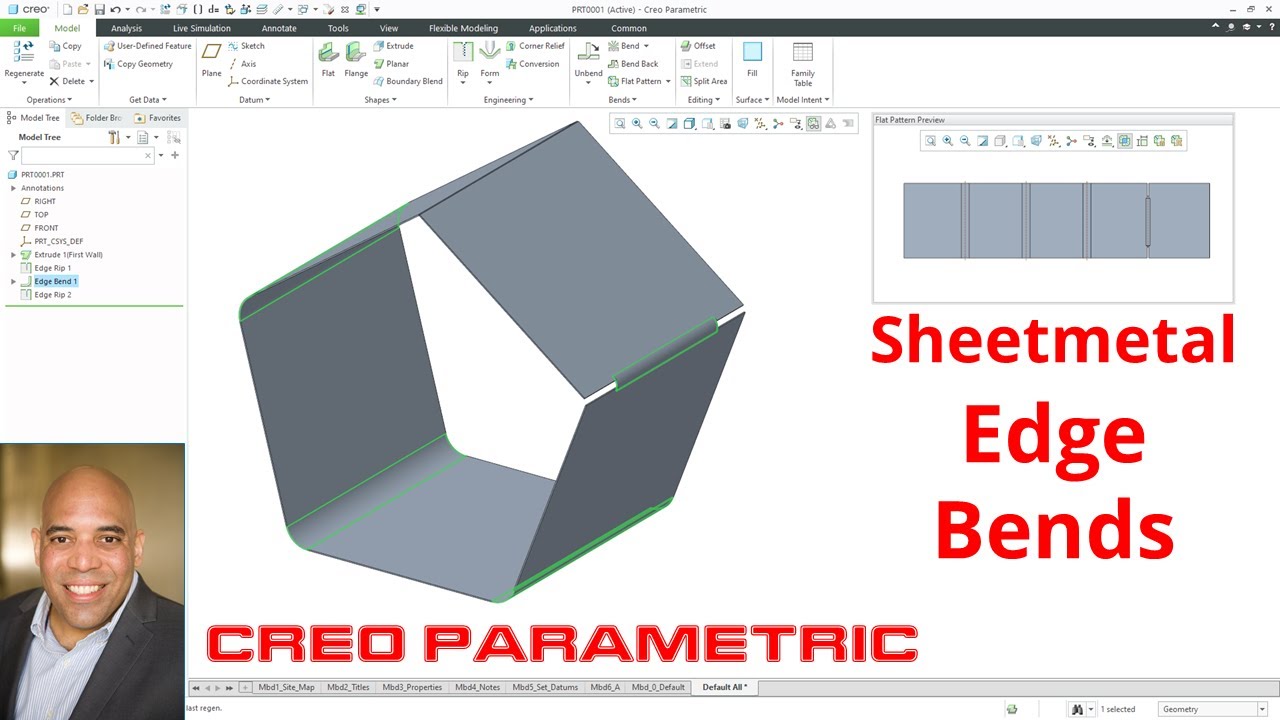
Creo Parametric Sheetmetal Edge Bends Youtube
Creo Parametric Basic Tutorial Sheet Metal Youtube
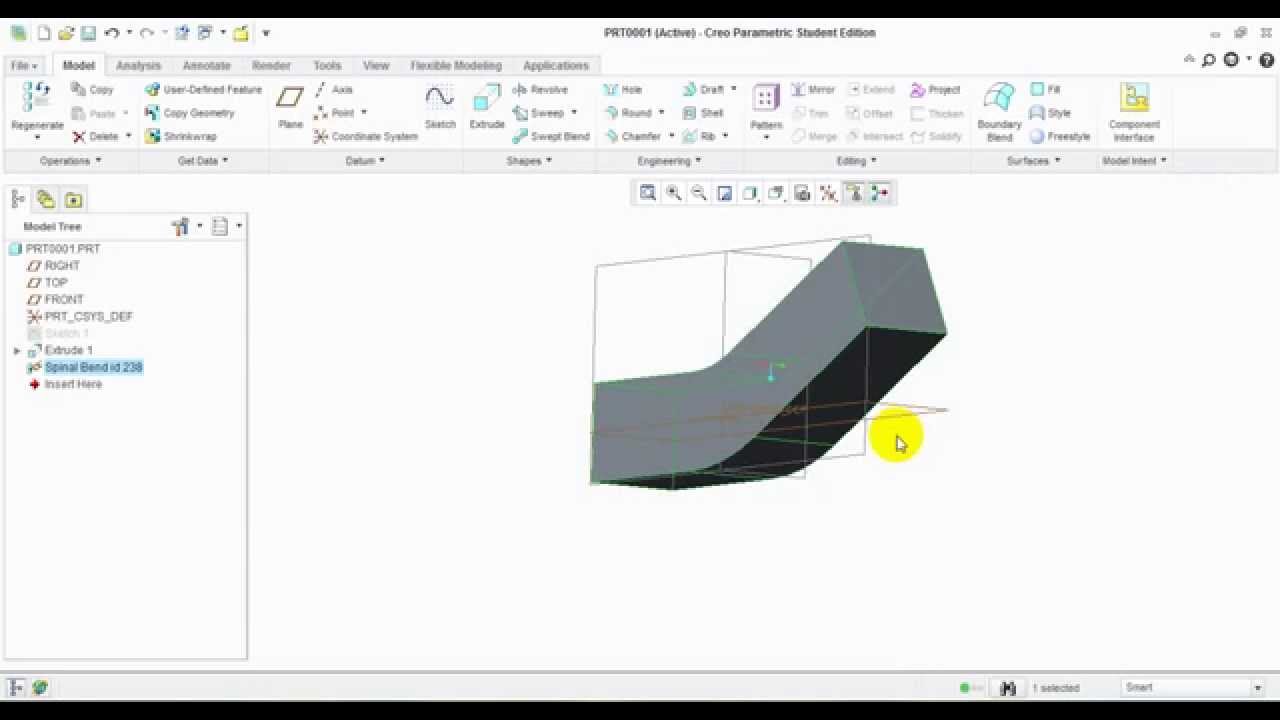
Spinal Bend In Ptc Creo 2 0 Youtube

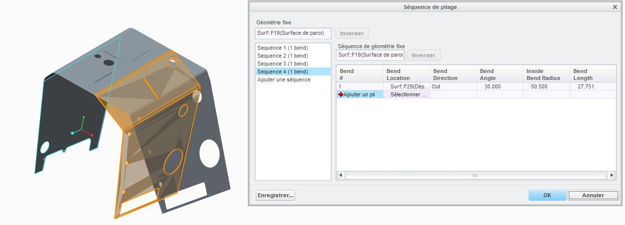
Bends are often generated automatically during the creation of wall features.
Bend sheet metal creo.

Creo Sheetmetal Tutorial Transition Unbends Youtube

Sheet Metal Flat States

Sheet Metal Modeling And Drawing In Creo Youtube
Solid To Sheet Metal Conversion In Creo 2 0 Youtube
Spinal Bend Creo 3 0 Youtube

New To Creo 4 0 Sheetmetal Design Edge Bend Is Improved In Sheetmetal Design Youtube
For Bended Sheetmetal Make Bend Parameters Availa Ptc Community

How To Create Sheet Metal Model With Drawing In Creo Youtube
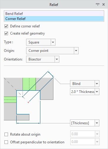
New Types Of Corner Reliefs
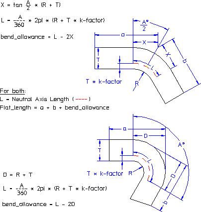
Allowance Tables And Formulas
How To Bend A Tab Up In Creo Parametric Ptc Community
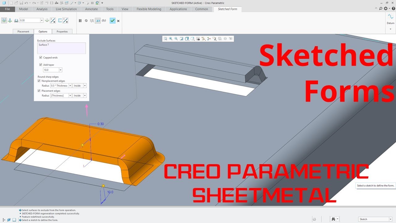
Creo Parametric Sheetmetal Sketched Forms Tutorial Youtube

Ptc Creo Elements Direct Sheet Metal Features
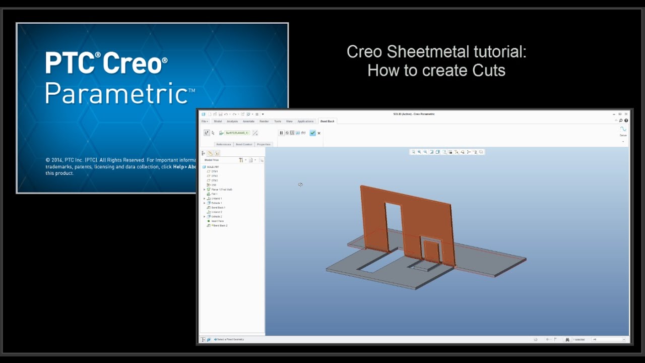
Creo Sheetmetal Tutorial How To Create Cuts Youtube

Planar Bend Sheet Metal Creo Parametric H Youtube

Flange All Types Command In Creo Sheetmetal Youtube

Creo 3 0 Sheetmetal Tutorial Extrude Feature Youtube

Creo Sheet Metal Rectangle To Ellipse Blend In Creo Parametric Youtube
Https Encrypted Tbn0 Gstatic Com Images Q Tbn 3aand9gcshvsmiewf8zz0llvgus01kk2qa0shi6v Iyk6p6dkf1rva6h9v Usqp Cau

Bend Edge Bend In Creo Sheet Metal Youtube

Creo Parametric 6 0 Sheetmetal Flat And Flange Wall Changes Youtube

Sheetmetal Transition Creo Youtube
Did You Know Ptc Creo 3 0 Enhancements Bend Tool Ptc Community
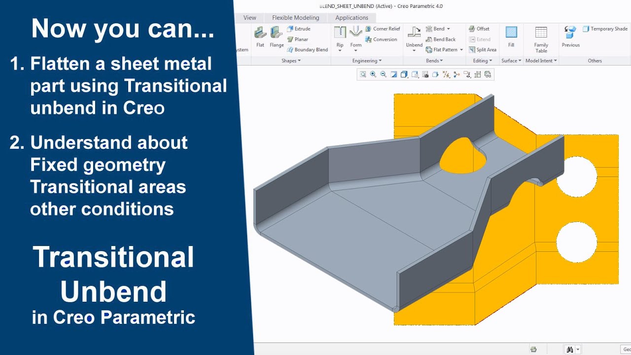
Creo Sheet Metal Transitional Unbend And Conditions In Creo Parametric Youtube
Source : pinterest.com
